Week 1
Allocation of Roles and Analysis:
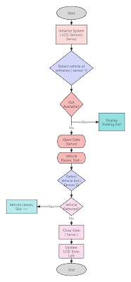
In week one, our group decided on what each member's role was in the project, ensuring a smooth workflow where everyone knew what each others responsibilities were. We drafted a basic circuit architecture diagram and started had finalised the intended logic flow of the smart car-parking system.
Team Members
Michael Bond
Yufei Fu
Yujin Cao
Amanah Mohammed J Abdulaal
Introduction
In preparation for the lab work, we designed a circuit diagram that can achieve the functions of the project. The smart car-parking system implements ultrasonic sensors to detect incoming and outgoing toy cars. One ultrasonic sensor is used to detect cars that are entering the car park, and the second sensor is used to detect cars that are leaving the car park. The system keeps track of how many spaces are available in the car park by subtracting one from the number of available spaces when a car enters the car park, and adds one to the number of available spaces when a car leaves the car park. When the car park has no available spaces, the gate will not open for cars that are trying to enter and a message willl display on the screen to say the car park is full. The screen will be a small 16x2 I2C LCD and the parking gate will be powered by a servo motor. All of the logic will be controlled by an Arduino Uno microcontroller
Logic diagram
Main Components
We completed the setup of the ultrasonic distance sensor and servo motor. The sensor detects vehicles within a set range, triggering the servo motor to open or close the gate as needed.
During testing, the gate opened when a vehicle was detected and closed once it passed. The servo adjusted the gate's angle smoothly, demonstrating the basic operation of our parking system.


Comments
Post a Comment